RS-Series DC Motors
While often semi-proprietary, the "RS" series (originally from Mabuchi) has become a global standard for small brushed DC motors. They are identified by their body diameter.
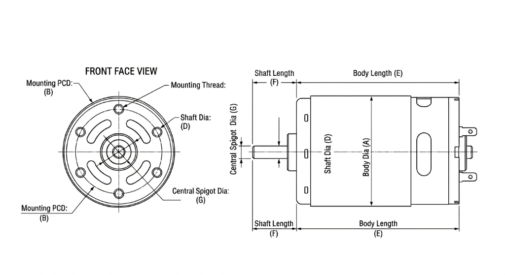
Standard RS Series Dimensions
| Series | Body Dia (mm) | Mounting PCD (mm) | Mounting Thread | Shaft Dia (mm) |
|---|---|---|---|---|
| RS-380 | 27.7 | 16.0 | M2.5 | 2.3 |
| RS-385 | 27.7 | 16.0 | M2.5 | 2.3 |
| RS-540 | 35.8 | 25.0 | M3 | 3.175 |
| RS-550 | 35.8 | 25.0 | M3 | 3.175 |
| RS-775 | 42.0 | 29.0 | M4 | 5.0 |
| RS-795 | 42.0 | 29.0 | M4 | 5.0 |
Design Parameters
- Body Diameter: Total width of the cylindrical motor housing.
- Mounting PCD: Typically two threaded holes on the faceplate.
Engineering Insights for Brushed DC Motor Integration
The "RS" designation, originally a nomenclature established by Mabuchi Motor, has become the de facto standard for cylindrical permanent magnet DC motors. While these motors are conceptually simple, their high-speed operation and mechanical commutation introduce specific electrical and thermal challenges that must be addressed in the design phase.
Commutation Physics and Brush Selection
Brushed DC motors rely on mechanical sliding contacts (brushes) to flip the magnetic field of the armature as it rotates. The material of these brushes dictates the motor's operating envelope:
- Carbon Brushes: Standard in the 500 and 700 series (e.g., RS-550, RS-775). Carbon is self-lubricating and can handle high current densities, making it ideal for power tools and high-torque actuators. However, they create "carbon dust" over time, which can eventually bridge the commutator gaps and cause short circuits in high-voltage variants.
- Precious Metal Brushes: Often found in the smaller 300-series motors. These offer extremely low starting voltages and lower electrical noise but are sensitive to high-current spikes and typically have a shorter total lifespan under heavy load.
Electrical Noise and EMI Suppression
Because the commutation process involves breaking electrical contact thousands of times per second, brushed motors are massive generators of electromagnetic interference (EMI). This noise can cause microcontrollers to reset or corrupt I2C/SPI communication lines.
A standard "best practice" for suppression is the Three-Capacitor Method:
- One 0.1μF ceramic capacitor soldered across the motor terminals.
- Two 0.1μF capacitors soldered from each terminal directly to the metal motor "can" (housing).
The can acts as a Faraday cage, while the capacitors shunt high-frequency spikes to the ground before they can propagate up the wiring harness.
PWM Frequency and the L/R Time Constant
Controlling speed via Pulse Width Modulation (PWM) requires careful frequency selection. If the frequency is too low, the motor will emit an audible "whine" and experience high torque ripple. If the frequency is too high, the motor's internal inductance will prevent the current from reaching the levels required for high torque.
Most engineers aim for a frequency between 15kHz and 22kHz—above the range of human hearing but low enough to stay within the switching limits of standard H-bridge MOSFETs. Be aware that at high PWM frequencies, switching losses in the motor driver increase significantly, requiring better heat-sinking for the electronics.
Armature Poles: 3-Pole vs. 5-Pole
Most inexpensive RS-series motors use a 3-pole armature. While cost-effective, 3-pole motors suffer from high "cogging torque" and can occasionally get stuck in a "dead spot" where the brushes bridge the commutator in a way that prevents starting under load.
Higher-end variants or those intended for precision control use 5-pole armatures. These provide much smoother rotation at low speeds, more consistent torque delivery, and a lower risk of start-up failure. When modeling a system that requires precise positioning or low-speed crawling, always verify the pole count.
Stall Conditions and Thermal Failure
The most common failure mode for an RS-series motor is a "thermal runaway" during a stall. In a stall, the Back-EMF (the voltage the motor generates as it spins) drops to zero, and the current is limited only by the wire's resistance.
A motor rated for 2.0A continuous operation might pull 30.0A or more at stall. This current generates heat ($I^2R$) exponentially. Within seconds, the insulation on the armature windings can melt, leading to an internal short. If your application has a high risk of jamming, you must implement over-current protection in software or via a hardware fuse (PTC).
Mechanical Mounting Nuances
- Shaft Loading: These motors utilize sleeve bearings (oilite) or small ball bearings. They are not designed for significant radial or axial loads. If your design uses a heavy belt drive or a large cantilevered wheel, you must use an external bearing block to support the shaft.
- Press-Fitting: When pressing a gear onto the shaft, always support the rear end of the shaft if it is exposed. Pressing against the motor can will often displace the rear bearing or crush the brush assembly, rendering the motor useless.
Common Standards Reference
| Series | Nominal Voltage | Typical Stall Torque | Target RPM (No Load) |
|---|---|---|---|
| RS-380 | 7.2V | ~40 mN·m | 15,000 |
| RS-540 | 12.0V | ~150 mN·m | 18,000 |
| RS-550 | 12.0V - 18V | ~400 mN·m | 20,000 |
| RS-775 | 18.0V - 24V | ~800 mN·m | 12,000 |
Note: Performance data is highly dependent on the internal winding (e.g., more turns of thinner wire vs. fewer turns of thicker wire).